Optical time reflectometer (OTDR)
It injects a series of optical pulses into a fiber under test. This light travels through the fiber to its end and is then reflected back to the OTDR. Depending on the scattered and reflected light, the device characterizes the fiber, its connectors, its splices and all other imperfections. The results of the measurements are displayed, among other things, on a graph showing the power of light as a function of time.
Note that the OTDR uses the same connector to generate the pulses as well as to capture the reflected pulses.
launching cable
The pulses generated by the OTDR have a certain duration. When the fiber under test is too short, the pulse may have time to reach the end of the fiber and then return to the OTDR before the generation of the pulse is complete. In this case, the device will be unable to measure the characteristics of the fiber in question.
Example: A pulse with a duration of 1000 ns will have a length of 100 meters. If an OTDR attempts to measure the characteristics of a 40-meter cable using a 1000 ns pulse, the pulse will have time to reach the end of the fiber and then be reflected at the OTDR before the pulse is completed.
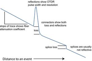
Fiber attenuation coefficient
The slope of the curve, when no vent is present, corresponds to the fiber attenuation coefficient expressed in dB / km.
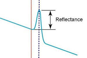
Reflection
A peak appears on the OTDR diagram when a reflection is detected. Reflection can be caused by, among other things, a connector or a mechanical splice.
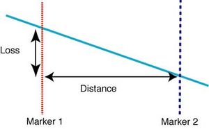
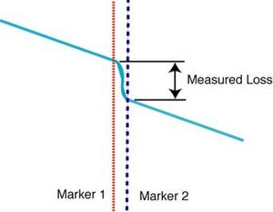
Loss
A loss is represented by a subsidence of the curve. A connector and a mechanical splice all produce losses. However, a splice (with a welder) can have such a weak attenuation that it will not be possible to see it at the OTDR.
Gain
A gain should not occur along an optical fiber, however it happens that an OTDR detects it. This completely normal phenomenon occurs when two fibers with different refractive indices are joined via a connection or a weld.
Ghost reflection
When a short fiber with one or more highly reflective connectors is tested, ghosts (reflection images) may appear. In fact, when a reflection occurs, it will propagate from one end to the other of the fiber until it is sufficiently attenuated to disappear under the noise floor. Before it is sufficiently weak, it may appear as a mirror copy called a ghost. The term ghost is used because the reflection event is not real, but rather a copy of another event.
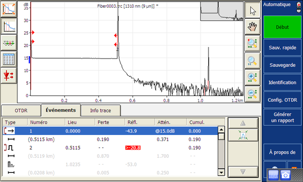
Example of curve with OTDR
We found in the OTDR data sheet that the standard attenuation of the launch cable per kilometer should be close to 0.37dB / km. Let's do a few tests to see if this is the case.
1) Once switched on, select the entry for automatic OTDR in the Mini Toolbox home page.
2) Then, to test the attenuation of the launch cable with the OTDR, simply plug one of the cable connectors into the SM socket and leave the other in a vacuum.
3) Press the start key to activate the laser which will test the cable in question.
4) Analyze the results: As shown in the diagram below, the red arrows respectively represent the beginning and the end of your thread. In between these we can see the attenuation results which will only be found in the cable. For our part, we obtained the following data: loss of 0.190 and an attenuation of 0.371 dB / km. Thus, we could see that the OTDR launch cable meets the standards seen on the technical sheet.